
Cat5 Poe Wiring Diagram
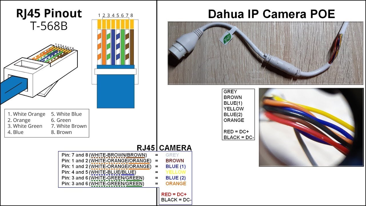
Pin 8 → brown wire. Various ethernet network cables are being invented.

Poe Cat5 Wiring Diagram
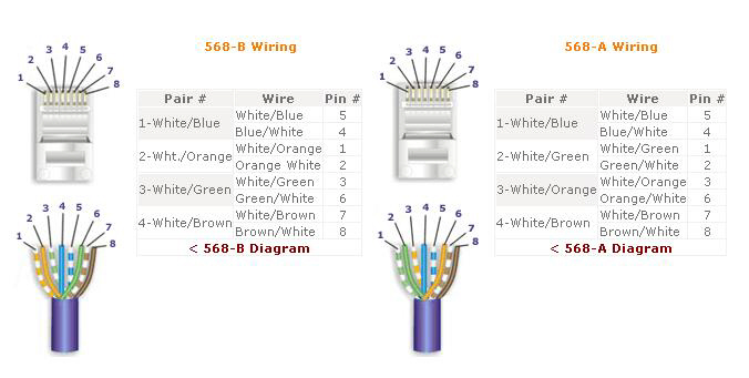
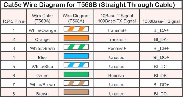
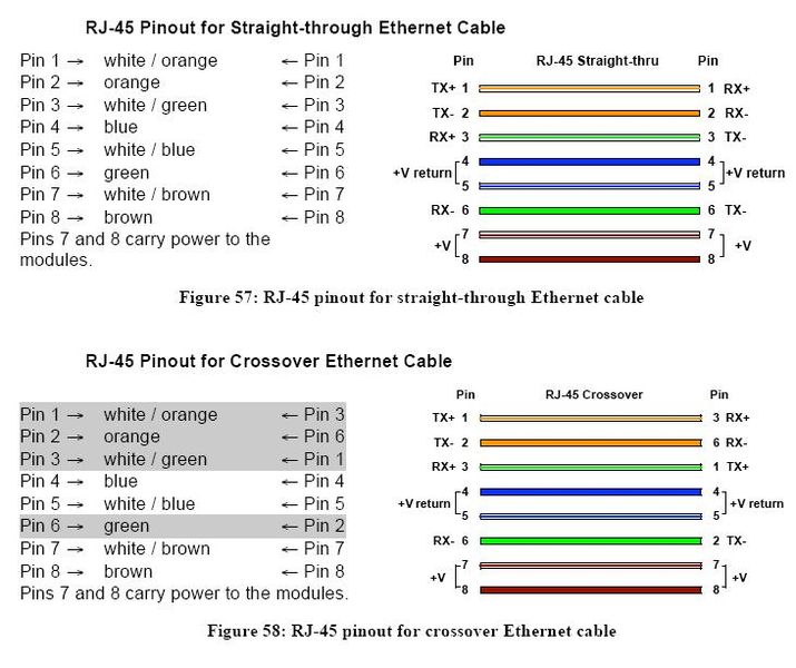
Pin 3 → white and orange (receive +) wire.

Cat5 poe wiring diagram. Wire both ends identical, 568b or 568a. There will be main lines that are represented by l1, l2, l3, and so on. As stated previous, the traces in a cat5e wiring diagram signifies wires.
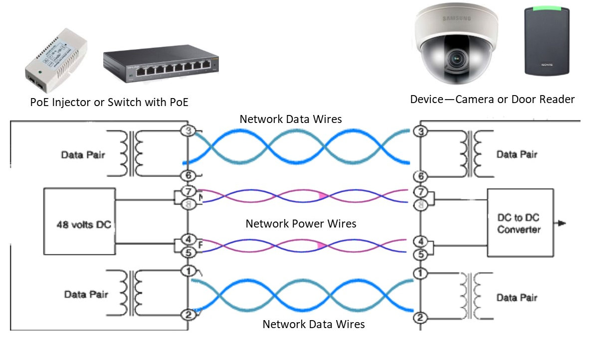
Image used courtesy of cisco. Remember that pin 1 is on the left hand side of the rj45 connector with the clip at the rear. They can support different transmission distances and applications.
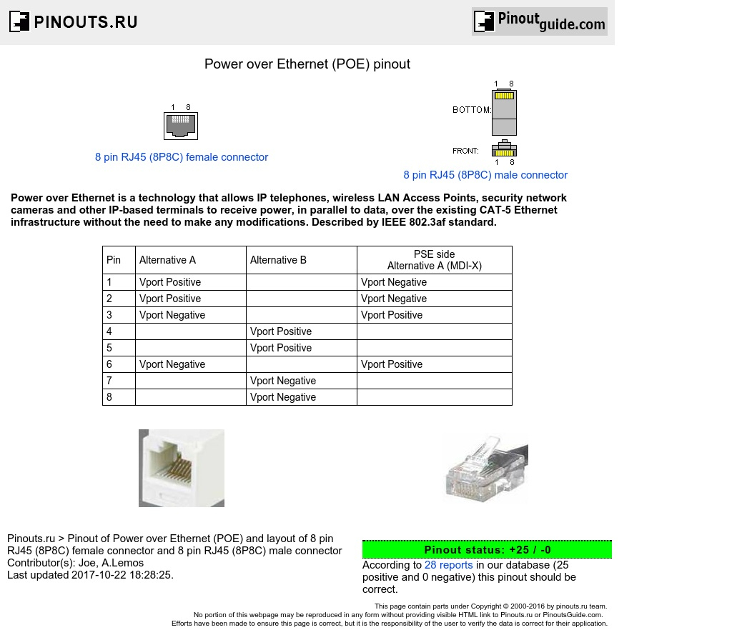
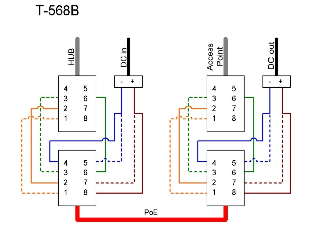
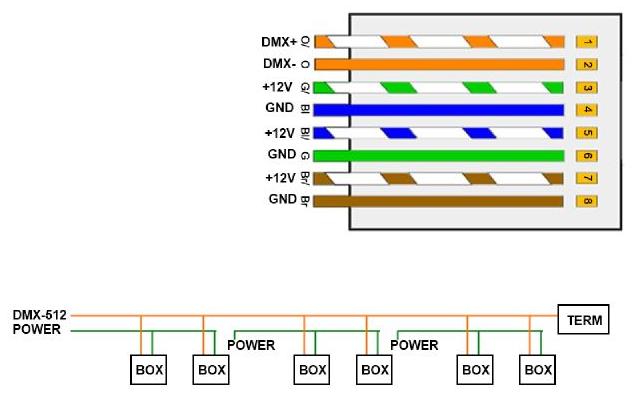
According to previous, the lines at a cat5 poe wiring diagram represents wires. A wiring diagram of power over ethernet configured in ieee's first standard. Power over ethernet is a technology.
Ip camera wiring diagram wiringdiagram today power over ethernet cable pins brilliant poe wiring diagram at cat5e hikvision 3332 i 3mp outdoor network mini dome ip camera 4mm poe poe wiring. The 802.3at standard is also known as poe+. For instance , if a module is usually powered up and it also sends out a new signal of fifty percent the voltage plus the technician does not know this, he would think he offers a problem, as he would expect a.
The cat 5 wiring diagram poe is designed particularly to streamline the procedure of wiring the electrical elements in an automotive vehicle. Pin 4 → blue wire. Pin 5 → white and blue wire.
Poe cat 5 wiring diagram. That is why it is also known as twisted pair networking cable. Injunction of two wires is usually indicated by black dot at the junction of two lines.
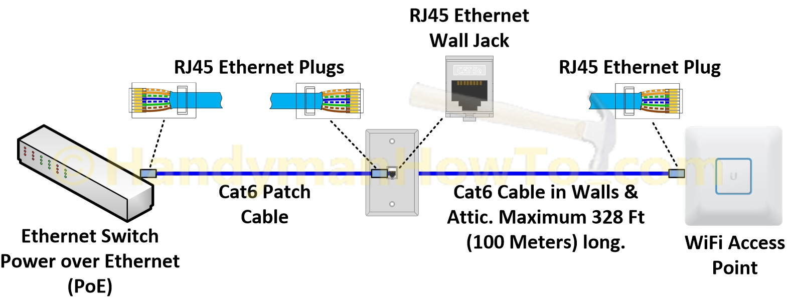
Network cables like cat5, cat5e and cat6 are widely used in our network. Sometimes, the wires will cross. Cat 5 network cable wiring configuration diagram straightthru:
The most commonly used form of cat5 cable is cat5e cable which supports the network bandwidth of up to 100mhz. 8 pin rj45 (8p8c) female connector at the hub. What is poe power over ethernet poe power over ethernet is the name of a number of methods that allow for powering network devices through utpftp cables.
Remember that pin 1 is on the left hand side of the rj45 connector with the clip at the rear. But, it does not imply link between the cables. In 2009, ieee released a new standard called 802.3at, setting the new threshold of power transmission at 25.5 w, effectively covering the entire range of applications.
It consists of guidelines and diagrams for various varieties of wiring strategies along with other items like lights, windows, and so forth. There'll be main lines which are represented by l1, l2, l3, and so on. Sometimes, the wires will cross.
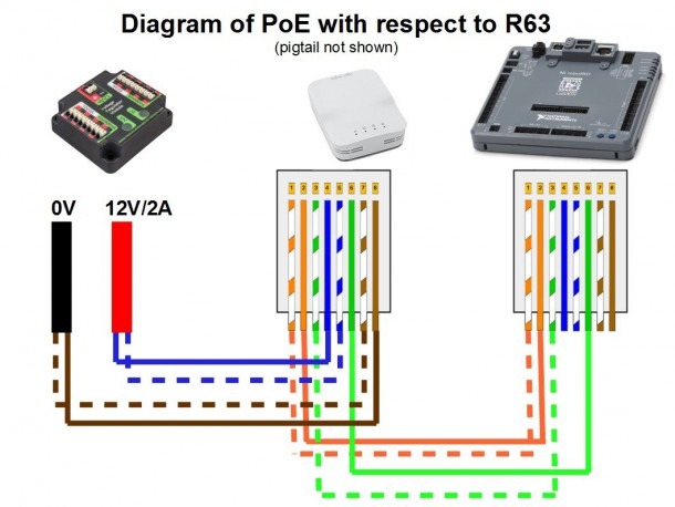
With such an illustrative manual, you will be able to troubleshoot, prevent, and full your assignments. Power over ethernet (or poe) is a technology that integrates data, voice and power note: Because a poe system alternative b uses the unused wires in a lan.
These directions will likely be easy to grasp and apply. It stands for the physical parts of the electric circuit as geometric forms, with the real power and link connections between them as thin edges. It's intended to help all of the common consumer in developing a correct program.
17 rows pinout of power over ethernet (poe) and layout of 8 pin rj45 (8p8c). Lan connections/pinouts are defined by ieee u. Cat5 cable or category 5 cableis the type of networking cable made by twisting the internal wires.
Injunction of two wires is generally indicated by black dot on the intersection of 2 lines. If you are searching for cat 5 poe wiring diagram, you are at the right site. Cat 5 poe wiring diagram.
Pin 7 → white and brown wire. We provide some wiring diagram for cat 5. But, it doesn't imply connection between the cables.
If you are searching for poe cat 5 wiring diagram, you are at the right site. Sargent a wiring representation is a basic graph of the physical connections and also physical design of an electric system or circuit. Cctv diagram ip camera poe injectors wifi bridges router no nvr dvr securitycamcenter com.
To properly read a cabling diagram, one provides to know how typically the components in the system operate. The cable transfers data with the speed of 1000. We provide some wiring diagram for cat 5.
What is a cat5 cable? 8 pin rj45 (8p8c) male connector at the cable. Poe ip camera wiring diagram power over ethernet poe technology enables powering ip surveillance cameras through the transfer of dc electrical and saves money by eliminating the expense and difficulty of direct.
Cat5 to hdmi wiring diagram.
How to access your DVR/NVR without a Router and Access IP cameras directly with an NVR with a
Cat5 Poe Wiring Diagram Cadician's Blog

19 Fresh Cat5 Poe Wiring

Wire Diagram 10

Poe Cat5 Wiring Diagram Wiring Diagram And Schematic Diagram Images
Cat 5 Poe Wiring Diagram Wiring Diagram
Ip Camera Cat5 Poe Wiring Diagram Database

Cat5 to Hdmi Wiring Diagram Gallery

Rj45, Wiring Diagram Brilliant Poe Wiring Diagram, 5 Dolgular Cat5 Within, HdDump.Me Photos
Poe Cat5 Wiring Diagram
Cat 6 Poe Camera Wiring Diagram CAT 5 WIRING DIAGRAM FOR POE CAMERA Auto Electrical

Wiring Diagram For Rj45
Cat5 Poe Wiring Diagram Cadician's Blog

What is PoE and How Power over Works in 2021 Cisco networking technology, Cisco

Poe Cat5 Wiring Diagram
Cat5 Wiring Diagram
ManualCat5/5e/6 Cable POE Connections CableFree RadioOS
[MB_6235] Images Of Cat5 Poe Wiring Diagram Wire Diagram Images Inspirations Schematic Wiring
Using cat5
